
How mobile C-arm clearance affects operating room equipment planning
A mobile C-arm may fit through the operating room door yet lack the clearance needed for positioning, rotation, and safe team access. For project managers, this makes mobile C-arm clearance a critical consideration in operating room equipment planning—not simply a final installation check. The device’s movement envelope, operating table compatibility, anesthesia workspace, and cable routes all influence equipment placement and workflow.
The practical question is not “Can we get the machine into the room?” It is “Can the team obtain the required images, with the patient positioned for surgery, without compromising access or repeatedly rearranging equipment?” Answering that question before procurement requires a coordinated review of the imaging system, table, room services, and planned procedures.
Clearance is a moving envelope, not a footprint
A floor plan showing the C-arm as a parked rectangle leaves out much of its operational space. The base must approach the table, the arm must reach the anatomy of interest, and the detector and X-ray tube must move through the required projections. Depending on the model, orbital rotation, angulation, vertical travel, and horizontal movement create different collision risks.
Distinguish three spatial conditions during design review:
- Transport clearance: the route through corridors, lifts, door openings, and turns, with the system in its specified transport configuration.
- Imaging clearance: the space needed to position the base and move the arm through the views required for the planned procedure.
- Working clearance: the remaining space for staff, sterile boundaries, anesthesia access, equipment operation, and emergency response.
These conditions overlap, but they are not interchangeable. A room may accommodate the machine mechanically while leaving no practical standing position for its operator. Equally, adequate circulation around a parked unit does not establish that a lateral projection will be achievable.
Start with the procedure and table configuration
Before comparing equipment dimensions, define the intended imaging tasks. Orthopedic trauma, spinal procedures, urology, and vascular work can involve different patient positions, anatomical coverage, and approach directions. “C-arm compatible” is too broad to serve as a room-planning requirement.
Ask the clinical team to identify the required views and where the machine must enter. Record whether imaging involves one region or movement along the patient, whether table tilt is needed, and which accessories remain attached. Where a system offers three-dimensional acquisition, its scan trajectory needs a separate clearance review; a successful two-dimensional positioning check does not demonstrate clearance for that trajectory.
Table compatibility deserves particular attention. A radiolucent tabletop does not mean the entire table assembly is unobstructed or radiolucent. The pedestal, base, rails, traction attachments, arm supports, and positioning accessories may restrict movement or enter the imaging field. Table height also changes the relationship between the patient, detector, tube, and C-arm opening.
Review the exact table and C-arm combination at the intended patient positions and working heights. Do not approve each item independently and assume compatibility follows. A pairing that works for one anatomical region may be unsuitable for another without repositioning the patient or table.
Build the layout around clinical access, not leftover space
Once the imaging positions are understood, overlay the people and equipment that remain in place during imaging. The anesthesia machine, airway circuit, monitoring lines, instrument tables, surgical lights, ceiling pendants, and mobile displays all compete for usable space. Their positions cannot be treated as interchangeable simply because they fit on the drawing.
A useful review shows the room in several states: patient transfer, surgical setup, imaging, and equipment withdrawal. For each state, identify who needs access to the patient and what must move. This exposes conflicts that a single “typical arrangement” tends to conceal.
For example, a proposed lateral approach may clear the table but occupy the anesthesia team’s access route. Moving the anesthesia machine may then place breathing circuits or monitoring lines across the C-arm path. That is a workflow conflict requiring clinical agreement, not merely a drafting adjustment.
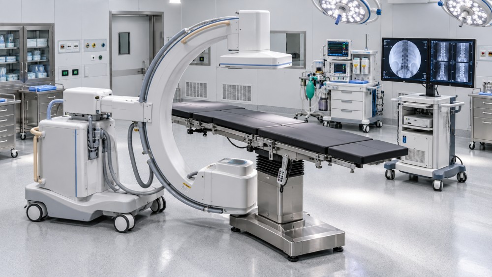
A coordinated plan should distinguish the C-arm’s movement envelope from staff working zones and routes that must remain available. Pair the plan with elevation or three-dimensional views where vertical conflicts are possible. Ceiling-mounted equipment can appear harmless in plan while obstructing the upper part of the imaging assembly.
There is no universal clearance figure that resolves every layout. Manufacturer instructions, the selected configuration, clinical activities, and applicable local requirements must determine the dimensions used. Avoid turning a supplier’s minimum mechanical gap into a general allowance for people, drapes, and workflow.
Obtain supplier information that supports a real fit check
A brochure usually cannot support detailed coordination. Procurement documents should request model-specific planning information, including optional components that change geometry. Confirm whether supplied drawings represent the offered configuration rather than a similar machine in the same product family.
- Transport details: overall dimensions in transport position, weight, maneuvering information, and any restrictions relevant to lifts, thresholds, or floor transitions.
- Movement geometry: arm opening and depth, detector and tube dimensions, movement ranges, and available swept-envelope drawings or digital models.
- Peripheral equipment: separate monitor cart dimensions, display adjustment ranges, connection arrangements, and permissible cart-to-system separation.
- Site requirements: electrical supply, connection locations, cable arrangements, environmental limits, and any model-specific installation conditions.
- Support space: access needed for cleaning, inspection, servicing, storage, and charging where applicable.
Ask suppliers to explain whether published movement limits are independently achievable or constrained in certain combined positions. Maximum travel in one direction does not necessarily mean the same travel remains available at every angulation. Collision-avoidance features, where provided, should not be treated as a substitute for layout validation.
Resolve cables, radiation protection, and parking early
Cable routing can undermine an otherwise workable arrangement. Power leads, interconnections, footswitch cables, and data connections need routes that accommodate repositioning without creating trip hazards or interfering with sterile areas. Check cable reach against every intended machine position, not just its parked location. Any proposed overhead support or floor-routing solution needs review for compatibility, cleaning, and safe use.
Radiation protection also has spatial consequences. Where mobile protective screens are specified, they need usable positions that do not block access, visibility, or movement. Structural shielding requirements depend on the installation, workload, adjacent occupancy, and local rules; they should be assessed by the appropriate radiation protection specialist or qualified medical physicist. The equipment’s mobility does not remove the need for that assessment.
Parking is another design decision, particularly when several rooms share one system. Identify where the C-arm and its accessories will wait, how they will be cleaned, and whether charging or electrical connections are required. A convenient corridor recess is not automatically acceptable storage, especially if it conflicts with circulation, fire safety, or infection prevention requirements.
Validate the sequence before committing to the purchase
Digital coordination is valuable, but its reliability depends on the quality of the models and assumptions. A simplified equipment block cannot prove rotational clearance. Keep unverified dimensions visible in the coordination record and assign responsibility for resolving them before design approval.
Where practical, arrange a demonstration with the proposed C-arm and table configuration. A full-scale mock-up can test staff positions and access, although taped outlines alone cannot validate vertical movement or under-table interference. Include representatives from surgery, anesthesia, radiography, nursing, clinical engineering, facilities, and infection prevention as appropriate.
Walk through entry, positioning, the required views, withdrawal, and patient access during an urgent interruption. Use representative accessories and account for draping, patient positioning aids, and the monitor cart. Record conflicts and agreed changes rather than relying on a general statement that the room “looks workable.”
Translate the outcome into procurement and acceptance criteria. These might require demonstration of specified projections with an agreed table setup, verification of the delivery route, and confirmation that cables remain clear of designated access paths. Site acceptance should use suitable simulation or test arrangements, follow manufacturer instructions, and avoid unnecessary radiation exposure.
Treat compatibility as a project deliverable
A lower purchase price is difficult to justify if the selected combination demands unplanned table replacement, relocation of services, or repeated room reconfiguration. Conversely, a larger system is not necessarily unsuitable if its movement geometry matches the procedure better. Compare complete working arrangements, not footprint or imaging specifications in isolation.
This systems-level evaluation reflects the procurement perspective of Global MedTech & Healthcare Intelligence Hub (MTHH): medical equipment value depends on application conditions, workflow compatibility, maintenance, and support as well as technical performance. Structured information helps project teams turn broad product claims into questions that suppliers and clinical users can answer together.
Before freezing the operating room equipment planning package, retain an approved layout, a procedure-specific clearance review, and an unresolved-issues register with named owners. If a critical projection or access route remains unverified, keep it open as a project risk. Passing through the door is a delivery milestone; demonstrating safe, workable positioning is the compatibility test.
- Last One:No more articles
- Next Article:What affects the cost of computed tomography systems in Saudi Arabia?Oct 16, 2026